

Introduction Fillet welds are the most commonly used weld types in marine structures.
October 12, 2023

Fillet welds are the most commonly used weld types in marine structures. A fillet weld is used when there are two pieces of metal that are joined perpendicular to each other or at an angle. In this article, we will explore how to select the right size fillet weld for the case when the pieces of metals are to be welded perpendicular to each other in a tee-joint. The article follows the requirements of Eurocode 3: Design of steel structure (EN 1993 Part 1)
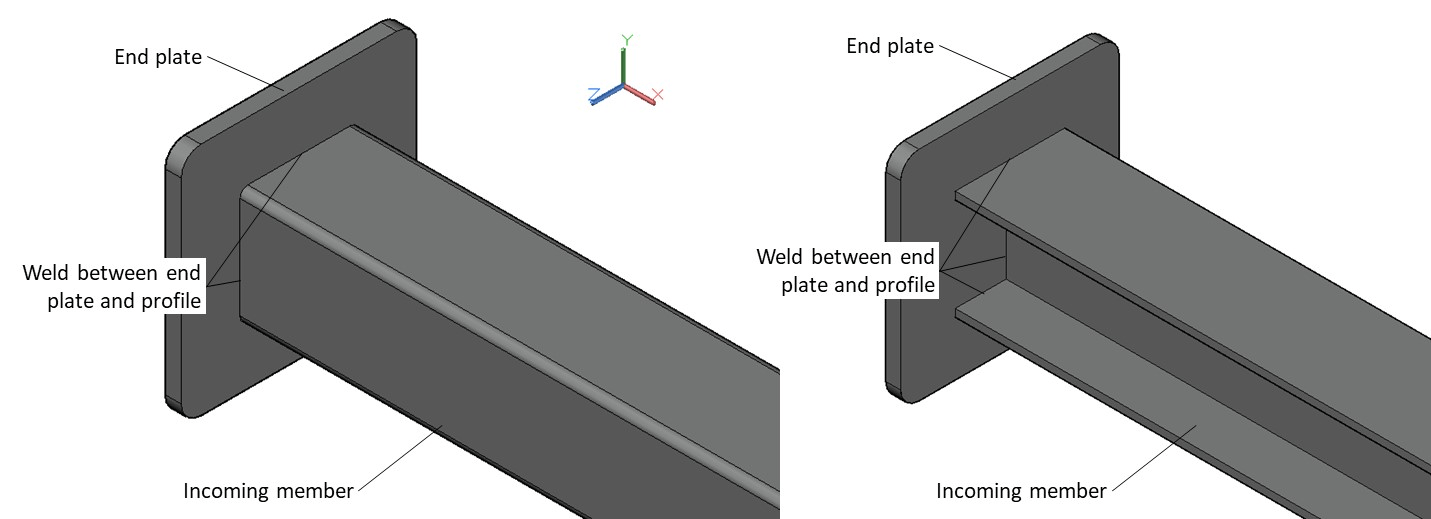
The fillet weld explored in this article is one that is between an incoming member and an endplate. This is shown in the figure below. The incoming member can have a different section shape: it can be an I-section or an RHS section (Rectangular Hollow Steel) or some other section. The method described in this article is only applicable to double symmetrical sections.
The material properties that are relevant will be the properties of the plate, and of the weld.
For the plate, the Yield Strength, Tensile Strength, and the material factor. The material factor γ is a safety factor that is applied based on EN 1993-1-1
For the weld, the Ultimate Strength is used for strength checks, together with a material factor γ and a correlation factor β that are applied based on EN 1993-1-1 and Table 4.1 of EN 1993-1-8 respectively.
Next, we take a look at the forces on the weld. Any structure will be subject to 6 degrees of freedom, each designated by a force/moment. The weld is subject to the following:
The section properties of the weld need to be computed for the stress checks to be done. These include the bearing area, shear areas, the moment of inertia about the two axes, and the section moduli about the two axes. Depending on whether the section is an RHS section or an I-section, the formulae for these properties will vary.
Once the section properties are calculated and the forces on the weld are available, we need to perform the stress checks on the weld.
There are different types of stresses that need to be checked:
Shear Stress due to Fy = Fy/(Shear area in the y-direction)
Shear Stress due to Fz = Fz/(Shear area in the z-direction)
Torsional Shear Stress = Axial moment x extreme axial distance/polar moment of inertia
The axial distance and the polar moment of inertia depend on the type of section selected, and can be calculated using standard formulae for the I-section or RHS section
The final stresses on the throat section of the weld can be summarized as below:
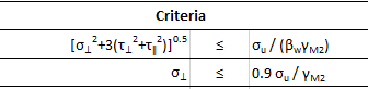
The criteria check against allowable stresses are provided below. These need to be met for the weld to be acceptable